Mitigating BESS Site Heat Island Effects to Ensure Reliable Operation
August 28, 2025

By Mitch Zafer, PE, PMP| Principal, Energy Storage | Seattle
In 2024, the US added 37.1 GWh of energy storage capacity, primarily from integrated battery energy storage systems (BESS). As these installations grow rapidly in number and size, a critical yet often overlooked aspect of BESS site design is how battery heat dissipates throughout the facility during the cooling process.
Generally, HVAC system designs for energy storage system (ESS) enclosures focus only at the enclosure level (often for one enclosure in isolation) and not for site level dynamics. It is important to consider the thermal effects that arise when multiple enclosures operate simultaneously in close proximity. If not considered, poor site planning can lead to overall facility storage capacity degradation and ultimately, a loss in profitability.
The refrigeration cycle within an HVAC unit in an enclosure works by moving battery heat from inside the enclosure to the outside. However, when the battery heat from millions of battery cells is rejected simultaneously in a confined space, it can significantly raise temperatures within the BESS facility.
This issue is amplified when the HVAC unit condensers blow warm air directly into the aisles between the enclosures, where it can become trapped. If the HVAC intake is also located in these aisles, it will draw in this recirculated hot air. As the intake temperatures rise, HVAC cooling capacity decreases. If the intake air temperatures are too high, the system may fail to adequately cool the batteries. This condition leads to battery capacity deration on the hottest days, usually when stored energy is most needed. This can lead to grid capacity issues and reduced project profitability.
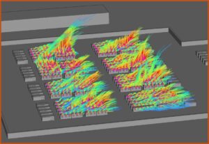
Modeling by Coffman Engineers and RandSIM shows that with typical 10-foot aisle spacing, unmitigated temperatures in these zones can reach up to 12°C above ambient, depending on wind conditions.

Due to the concentration of solar and wind generation in the hottest regions of the country, many BESS facilities are constructed in locations with extreme temperatures often near the maximum design limits for ESS enclosure HVAC units. To provide reliable delivery of negotiated power and energy capacities year-round, developers must evaluate the potential heat accumulation across the entire site. This analysis should be tailored to the specific facility layout and technology in use.
Engineering analysis of heat accumulation is typically conducted using computational fluid dynamics (CFD) modeling. For accurate modeling, it’s critical that model inputs are both detailed and accurate.
HVAC-Level Inputs
The first category of input assumptions involves the HVAC unit. It is not as simple as taking the battery heat dissipation per enclosure and blowing it into the aisles. The inefficiencies in the refrigeration circuit significantly increase the total heat rejected into the aisles, necessitating a deeper analysis of the particular HVAC unit model.
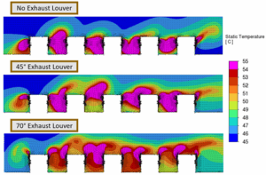
The velocity profile across the exhaust louver and the angle of the louver blades determine where the hot air is being directed. The cooling diversity and battery C-rate (as compared to the factory enclosure design) could make a difference in decreasing the heat island effect.
There are many more details that can make the difference between staying within the enclosure manufacture allowable temperature limits or exceeding them and potentially violating utility capacity contracts.
Site-Level Inputs
In terms of site level inputs, there are several important factors. Annual wind profiles can have a significant effect. It is not always intuitive as to which wind direction and speed will lead to the worst outcomes and correlate with the hottest yearly temperatures.
Additionally, facilities with tall perimeter sound walls, or different topographies, can lead to localized wind speed reduction throughout the BESS yard, resulting in increases in air temperatures.
Another factor to consider is where the inverters are located in relation to the BESS enclosures. Inverters generally exhaust high-temperature air through multiple-louvered outlets. If positioned where the exhaust can get into the aisles between the BESS enclosures, they can contribute to systemic overheating across the site. To identify worst-case scenarios, multiple CFD analyses should be performed.
When planning a BESS site and selecting an enclosure manufacturer, two of the most effective mitigation strategies are:
1. Large aisle widths
2. Selecting an enclosure model that directs hot condensed air upward
However, these options may be limited due to site area constraints and available or economical enclosure manufacturers. In these cases, mitigation must focus on the HVAC unit condenser exhaust.
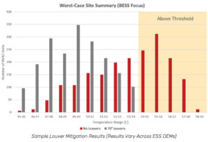
Mitigation options include increasing the louver angle or adding ductwork attached to the condenser exhaust. If either of these solutions are implemented, proper analysis of their effects on the performance of the HVAC unit is needed.
Both approaches introduce pressure drop which can reduce airflow across the HVAC unit condenser section. If not properly designed, this solution could lead to greater performance degradation.
It’s a balancing act when implementing a successful solution. With proficient engineers and CFD professionals incorporating these aspects into their analysis, effective solutions are generally achievable.
Images courtesy of RandSIM.
For more details or project specific guidance, contact us. We’re here to help!

Coffman is a locally driven engineering firm reinforced by a national network of multidiscipline capabilities. Our teams and processes scale quickly and move nimbly, allowing us to provide engineering solutions that are smart, practical, efficient, and have a positive impact on cost, scope, and schedule.
Contact Us
We’re entrepreneurs at heart who want to see your business and community thrive.
We draw upon our large network of talent to strive for excellence at every step.
Learn More
The right tools.
The right environment.
The right people.
Apply Now
Take a moment to review some of our news items and learn more about Coffman and our clients.
Stay Connected


