Continuous Emissions Monitoring System (CEMS)
January 13, 2026

By Michael Lee, PE | Senior Engineer, Electrical Engineering, Instrumentation and Controls | Dallas
Upgrading aging Continuous Emissions Monitoring Systems (CEMS) in fossil generation power plants is important for maintaining environmental compliance and operational efficiency. This technical article details best practices for planning, design, and installation intended to deliver a reliable, long-lasting system while limiting disruption to plant infrastructure and operations.
Generating electrical power is an essential utility that facilitates the daily operation of our modern-day society. Without it, the present day first-world standard of living, as currently structured, would not exist. From communications and transportation, to manufacturing and healthcare, our society is built upon the provision of reliable, inexpensive energy. Along with maintaining successful facility operations, electrical utilities are mandated to provide a record of greenhouse gas emissions for government review, oversight, and recordkeeping. Electrical generation utilities can maintain commercial operation only by complying with this federal requirement, which includes using a Continuous Emissions Monitoring System (CEMS).
Maintaining CEMS compliance for emissions monitoring allows fossil generation plants to focus on maintaining and upgrading critical facility infrastructure to serve the community effectively. As with any system that provides monitoring capabilities, it is paramount to be mindful of the average lifecycle of CEMS equipment components and obsolescence schedules. Specifically, as equipment within fossil generation plants ages, challenges may arise in maintaining compliance with the mandated environmental requirements. To mitigate these challenges and keep systems in optimal operating condition, upgrades made to existing CEMS are pre-planned during scheduled construction outages, to avoid unexpected component failures. Upgrades also provide an opportunity to harness the most recent developments in emissions monitoring technology. Therefore, thorough planning and evaluation ahead of time is required upfront to deliver an accurate, long-lasting CEMS.
Older CEMS in plants can become problematic as replacement parts grow scarce or unavailable due to obsolescence. Rather than attempting to locate these individual components to maintain the existing system, it is more cost-effective for utilities to upgrade the entire CEMS with new equipment, including components such as the exhaust gas umbilical, programmable logic controller (PLC), and sample conditioning panel. Using an Issue for Bid (IFB) specification, an owner can competitively bid equipment procurement cost among multiple CEMS vendors. When written effectively, this IFB specification can clearly outline the material requirements and equipment installation constraints associated with the existing facility infrastructure. In addition to alleviating existing maintenance issues, a new system can maintain the power plant’s compliance with current reporting and certification requirements as governed by the U.S. Environmental Protection Agency (EPA).
Complete system upgrades require significant coordination and planning to achieve success. Given the commercial impacts of extended downtime, a thorough IFB specification, an accurate engineering detail design package, and a comprehensive project milestone schedule are vital for reducing outage duration and optimizing system functionality during the transition to in-service operation. Preparation begins with understanding system deficiencies and determining if increased monitoring capabilities are required. Whether the project scope dictates an in-kind equipment replacement or a system functionality augmentation, it must be clearly defined and agreed upon by all project stakeholders at the start of the detail design phase.
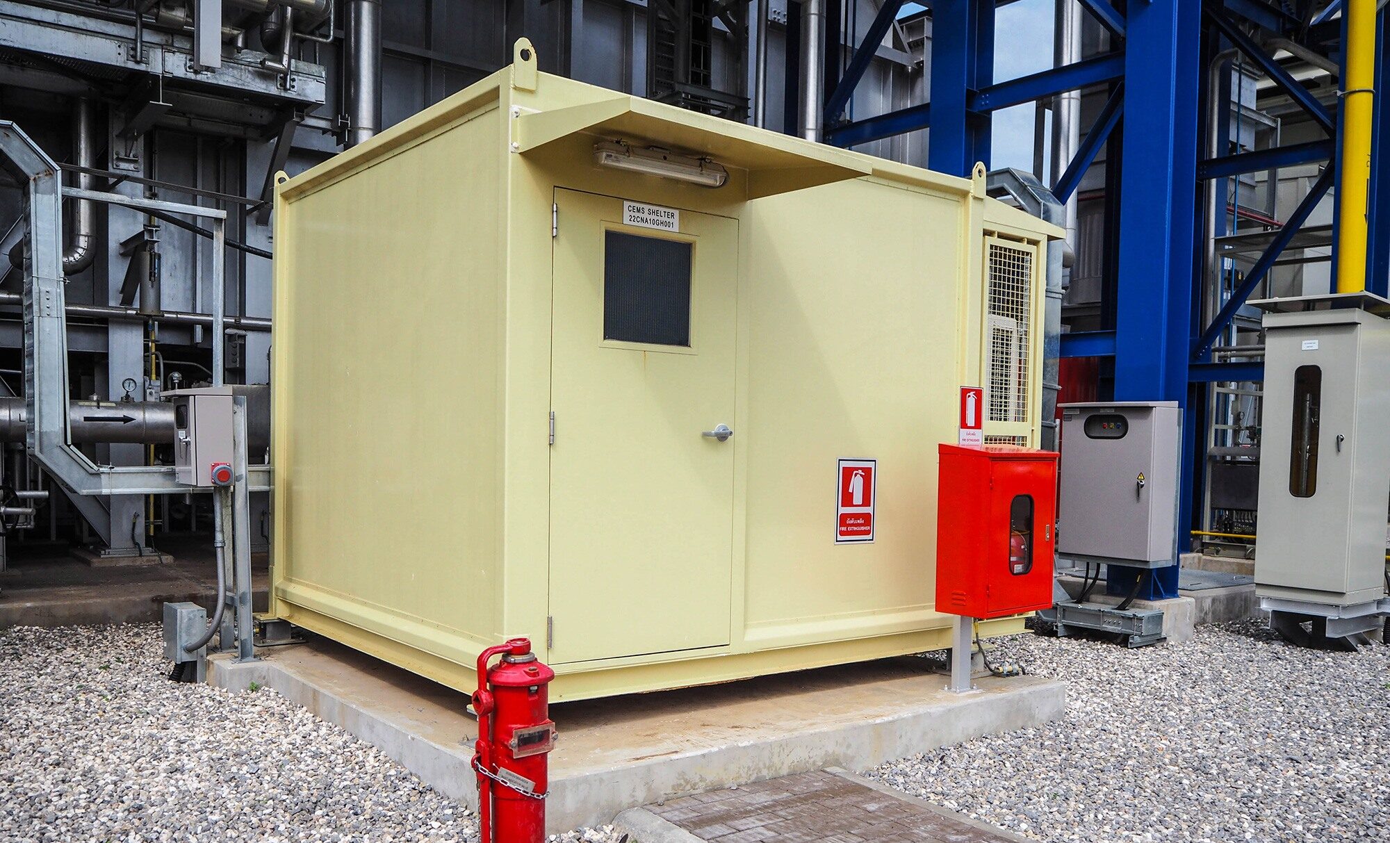
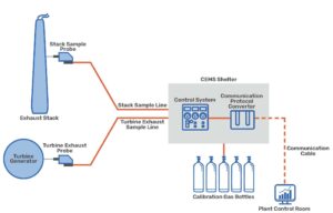
For example, if an existing system has an outlet stack port monitored by the CEMS, but no existing turbine exhaust port monitoring capability, the utility may want to augment monitoring capabilities. This means there would now be two different monitoring components, the stack and the turbine exhaust, and each would require CEMS equipment (one sampling conditioning panel and an exhaust fan per connection point). Oftentimes, the newer quick start gas combustion generation units will have both turbine exhaust and stack monitoring ports present. Depending on the number of monitoring point connections, the CEMS equipment vendor will have to furnish the appropriate quantities. Also, evaluating available unoccupied space inside the existing CEMS shelter is critical to confirm sufficient room for installing new equipment, especially when adding monitoring point connections.
To identify potential scenarios which could impact design scope, a comprehensive walkthrough of the CEMS shelter, stack, and turbine exhaust port locations of interest is required. This walkthrough is accompanied by a full review of existing CEMS design drawings, including plan views, electrical schematics, I/O lists, loop drawings, instrument lists, and electrical panel schedules.
During this process, existing shelter dimensions, proposed design components, data communication preferences, existing infrastructure such as cable trays, calibration gas bottle racks and slab dimensions, and future power requirements are verified.
By successfully executing these design elements and completing all deliverable documents, the installation, commissioning, and start-up of new CEMS can be achieved effectively. Following best practices during project kickoff, the IFB specification effort, and the detail design phase allows engineering service providers to deliver long-lasting, safe, and efficient CEMS capable of reliable environmental monitoring for electrical utilities.
For more details or project specific guidance, contact us. We’re here to help!
Coffman is a locally driven engineering firm reinforced by a national network of multidiscipline capabilities. Our teams and processes scale quickly and move nimbly, allowing us to provide engineering solutions that are smart, practical, efficient, and have a positive impact on cost, scope, and schedule.
Contact Us
We’re entrepreneurs at heart who want to see your business and community thrive.
We draw upon our large network of talent to strive for excellence at every step.
Learn More
The right tools.
The right environment.
The right people.
Apply Now
Take a moment to review some of our news items and learn more about Coffman and our clients.
Stay Connected


